Please
Note: This page is a work in progress. It is simply collection of notes and reference links I'm using to help me better
understand the rendering process. This page is a starting point and will be expanded upon as I learn more and therefore some things may be incorrect or incomplete. If
they are please let me know and I'll update the page.
The Electromagnetic Spectrum
and Electromagnetic Waves
Michael
Faraday, (1791 – 1867), was a British scientist who invented a way to visually depict electric
fields around a charge. Positive charged field lines point
radially outward and negatively charged lines point inward.
Interesting
guy with an interesting story:
Faraday's theories of
electric and magnetic fields were later put into a mathematical form
by James Clerk Maxwell who showed light to be an oscillatory
electromagnetic disturbance.
James
Clerk Maxwell (1831 – 1879)
The red plain (magnetic field) points up/down on
the Y axis, the blue plain (electric field) points in/out on the Z axis whilst
the X axis represents velocity. They are perpendicular to one another.
In reality the magnetic field is much
smaller than the electric field.
The color of visible light is
tied to its wavelength. Light within the visible spectrum runs from violet
which has a wavelength of Approx 7.5x10^14 Hz (approx 400nm) to red
which is about 4x10^14 (approx 750nm) Hz. Gamma rays are an example
of extremely high frequency (Approx 10000 times stronger than a visible light
ray), and radio waves are an example of low frequency. The higher the
frequency the higher the energy which is why gamma rays are so dangerous.
Light
travels at 3x10^8 (300 million m/s) - Velocity = Frequency x Wavelength. White
light contains all wave lengths and different wavelengths are refracted and
absorbed at different rates depending on the material.
Light
Frequency Wiki:
Refraction
Wiki:
Absorption:
The classical picture of
light therefore treats light as a wave where wavelength relates to colour
and amplitude relates to Intensity(brightness).
Light, however, behaves like both a wave and a particle depending on how it's observed .
Particles
of light are called photons and the energy of a single photon is measured by
the number of photons per time interval (frequency) x Planck's Constant.
Planck
Constant Wiki:
The Photoelectric Effect
"Einstein noted that the photoelectric effect depended on the wavelength,
and hence the frequency of the light. At too low a frequency, even
intense light produced no electrons. However, once a certain frequency
was reached, even low intensity light produced electrons.... He then postulated that light travels in packets
whose energy depends on the frequency, and therefore only light above a
certain frequency would bring sufficient energy to liberate an electron"
The photoelectric
effect is interesting because it highlights the problem with the classical model
where electrons, when irradiated by
light, should be ejected so long as the intensity (amplitude) is
big enough, regardless of the lights wavelength frequency. The maximum amount of kinetic energy should increase with the
amplitude but, in reality, it's photon frequency that matters and not the
waves amplitude(brightness).
Photoelectric
effect Wiki:
Einstein's contribution
Wiki:
Wave-particle
duality:
Planks
Constant Wiki:
Interference Patterns
The double
split experiment showed that, although light is detected as
particles, the interference patterns are wave like.
Wave
Particle Duality Wiki:
Lights and Temperature
"A black body (also blackbody) is an idealized physical
body that absorbs all incident electromagnetic radiation"
https://en.wikipedia.org/wiki/Black_body
Even if all
light is absorbed by an object it will eventually start to glow. As an
objects temperature increases and object emits light as blackbody radiation.
Objects emitting blackbody radiation will glow at the same color so long as
they are at the same temperature irrespective of material type.
In reality
no object can absorb 100% of the light. Some light is always reflected.
Charcoal is an example of material that behaves like a blackbody.
Black-body
Radiation Wiki:
Colour
Temperature Wiki:
The Kelvin scale
Increase
in temperature = Increase in brightness + the dominant wavelength shortens.
For example in the following graph the line for 7500K shows most of the light
being given off in the shorter wavelengths within the visible spectrum. Infrared
light is also given off which is why humans can be seen in darkness with
infrared cameras.
Temperature
curves peak at different wavelengths.
By
utilizing these relationships the temperature of an object approaching a black body can be worked out.
For example the sun:
Similarly different lights/film stock
are associated with different temperature on the Kelvin scale:
Photographic
daylight is around 5500K while around 3200K is associated with Tungsten
lighting.
Wien's displacement law:
Kelvin Wiki:
A scene
may have many different light sources and yet the white balance can only be set
for one color temperature which will result in color shifts relative to these
lights throughout the scene.
In
the following image a Kelvin scale has been drawn showing
the relationship between color and degrees.
Image sourced from:
Reflection, Absorption and
Refraction
Different
materials absorb some wavelengths of visible light and not others. The
wavelengths that aren't absorbed are bounced of the surface giving the
object its color.
The chlorophyll in
leaves, for example, is bad at absorbing green light but really good at
absorbing blue and red light as shown in the following graph.
Diffuse, Specular and Glossy
Reflection and Transmission/Refraction
"100 materials whose BRDFs have been measured and stored for academic research. 50 of these materials are considered "smooth" (e.g. metals and plastics) while the remaining 50 are considered "rough" (e.g. fabrics).
Source:
Of interest
BSDF - Bidirectional Scattering Distribution Function
BRDF - Bidirectional ReflectanceDistribution Function
BTDF
- Didirectional Transmittance Distribution Function
"The interaction of light with a surface can be expressed as a single function, called the bidirectional reflectance distribution function, or BRDF for short [Nicodemus77]. This is a function of four angles, two incident and two reflected, as well as the wavelength and polarization of the incident radiation".
Gregory Ward - Measureing and Modeling Anisotropic Reflection
Terms:
Incoming Light & Incident angle
Outgoing light and angle of reflection
Viewer position
Descriptions:
Isotropic reflections
Anisotropic reflections
Fresnel Reflections
Micro-facets
Specular Reflection
A mirror
is a perfect example of a specular reflection. A mirror has a smooth surface
that, ideally, doesn't absorb or scatter light although marble is also a smooth surface due to a scattering process that happens beneath its surface, it can never
be mirror like.
Specular
reflections depend upon the angle of view relative to the surface normal - "...the
direction of incoming light (the incident ray), and the direction of outgoing
light reflected (the reflected ray) make the same angle with respect to the
surface normal, thus the angle of incidence equals the angle of
reflection".
Specular Reflection Wiki:
Diffuse Reflection
Diffuse
reflection is light that has been reflected and scattered in many different
angles. The effect is a matte reflection. Diffuse light is less viewer dependent
than specular reflection because light that has been scattered evenly
in all directions will look the same from all directions. This scattering
of light is largely due to light entering the surface, bouncing
around and exiting in a diffused state.
An example
of a diffuse surface would be Tissue Paper.
Diffuse
Reflection Wiki:
In
computer graphics diffuse light is scattered in 180 degrees
which often looks unnatural and artificial.
Diffuse Transmission
BSSRD - Bidirectional Scattering-Surface Reflectance Distribution Function
Diffuse
transmission (or subsurface scattering) is where light enters the
surface of a translucent object, scatters and exits at a different angle
in a diffused state.
Source:
In
the case of skin, for example, light interacts with the epidermis,
dermis and subcutaneous layers beneath the skin's surface - more
specifically with the pigment in the epidermis and the blood vessels in the
dermis.
The pigments found in the epidermis include
Caroten, which is carrot orange, and Melanin which is brown or black.
Melanin is produced by melanocytes and the production of melanin is
increased by sun exposure.
Dermal circulation of red
oxygen rich blood gives a red tint to skin. When our blood vessels are
more dilated our skin becomes red and when our blood vessels are
constricted our skin becomes pale.
Glossy Reflection
Most
objects have a combination of both diffuse and specular reflections. Glossy
reflections are a mix between the two where the highlights of
light sources can clearly be seen but the reflection is
blurry and undefined. Glossy reflections are semi-specular or semi-diffuse
reflections.
Realtime rendering of glossy, shiny smooth and rough surfaces - visual examples.
Source:
Glossy reflections
are not only dependent upon the viewers perspective relative to the
surface normal but also upon the distance that any reflected objects, or
parts of objects, may be from the surface upon which they are being
reflected.
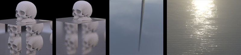
The following render of a metal pole reflecting off a mirror like surface shows glossy reflection increasing with distance.
Transmission/Refraction
Transmission
is the fraction of radiation directly transmitted through an object and refraction is the change in the propagation of light due to its
transmission medium.
As light passes between two separate mediums it
will either slow and bend towards the surface normal, (eg: air to
water), or speed up and bend away from it, (eg: water to air) .
In the
following image "light waves from X change direction and so seem to
originate at Y".
Source:
Snell's Law
Snell's
law relates angles of incidence to refraction. If we know the refractive index
for air and water, along with the angle of incidence, we can work out the angle
of refraction using Snell's formula.
There is also an online calculator for performing
Snell's law:
A list of IOR's for common materials
"Snell's law seems to require in some cases (whenever the angle of
incidence is large enough) that the sine of the angle of refraction be
greater than one. This of course is impossible, and the light in such
cases is completely reflected by the boundary, a phenomenon known as total internal reflection.
The largest possible angle of incidence which still results in a refracted ray is called the critical angle; in this case the refracted ray travels along the boundary between the two media."
Source:
Snell's law can be used to calculate the critical angle by setting the refraction angle to 90.
Specular And Glossy
Transmission/Refraction
As with specular reflection, specular transmission produces a clear refraction of
light and, as with Glossy Reflection, Glossy transmission is refracted light
that has become semi-diffused. The further into the surface the light penetrates the more diffused (blurry) it
will become.
Frosted glass is an good example of glossy transmission.
Anisotropy
Anisotropic
reflections are often seen on brushed metal surfaces where small
parallel surface grooves give the appearance that the reflection is being
stretched or pulled in a particular direction.
The reason
for this can clearly be seen in the following image:
If each
parallel groove where to be represented by a half torus then we would see
the specular highlight repeated on each creating the appearance of it being
stretched (1 & 2). In other words, on a surface where
parallel grooves run horizontally, the light will be reflected
over and over again causing it to look stretched (4) as opposed to a smooth surface (3) where it doesn't.
Hair is example of this:
Another
example of anisotropic reflections:
Fresnel Reflections
Augustin
Jean Fresnel (1788-1827), an early advocate of the classical wave
theory of light, invented equations to describe the reflectivity of smooth
surfaces. More specifically "Fresnel equations describe what fraction of the light
is reflected and what fraction is refracted (i.e., transmitted). They
also describe the phase shift of the reflected light".
The effect is less apparent for materials such as metals but
obvious for dielectric, non-conductive surfaces. For plastics, shiny
leaves, and glass with refraction indexes of around 1.5, for example,
the normal angle of reflectivity can be as low as 4% but as high as 100%
at glancing angle.
Typically the more grazing the angle the more light reflects instead of refracts.
Further reading:
Most
3D render engines handle Fresnel correctly for dialectic materials but
fail with non-dielectric materials such as gold or copper.
The reason has to do with a variable called k "extinction coefficient"
which is the "imaginary part of the complex index of refraction" and
relates to light absorption.
In addition non-dielectric materials reflect wavelengths differently. For example
copper reflects more red than blue or green.
Further reading
A discussion of this failing and how to correct for it in Maya can be found here:
http://therenderblog.com/custom-fresnel-curves-in-maya/
Here is the script. It was written for Arnold but can be easily altered for other Maya render engines.
A discussion of the script written to generate physically accurate Fresnel curves for metal can be found here:
The discussion linked to above also includes a way to check the reflection curve for any given IOR.
1. Write
a script that creates and rotates 90 poly planes in the X axis -
0 to 90 degrees (1).
2. Create a 100% white dome light with no
shadows and apply a shader with no diffuse and an IOR value of your
choosing.
3. Render from a top view orthographic camera (2).
4. In
nuke take the render and add a color sampler node to it (3).
5. Compare the resulting curve corresponding to your IOR here (Reflection calculator):
Energy Conservation
The
total reflection, refraction and diffuse contribution should always be
equal or less then the total contribution of light hitting the surface.
An Arnold User Guide image showing correct and incorrect energy conservation:
A
seemingly obvious thing to say but, considering most 3D shaders allow
the artist to "break" such physical laws and make a surface 100%
refractive and 100% reflective at the same time, it's worth noting.
Chromatic Aberration
When
light enters the lens of a camera different wavelengths of light can
refract at different angles. The result is that "fringes" of color can
be seen "along boundaries that separate dark and bright parts of the
image, because each color in the optical spectrum cannot be focused at a
single common point.Since the focal length f of a lens is dependent on the refractive index n, different wavelengths of light will be focused on different positions".
Chromatic Aberration increase as the power of the lens increases.
Image sourced from:
https://en.wikipedia.org/wiki/Chromatic_aberration
Shader Models
1. Lambert
2. Phong
3. Blinn-Phong
4. Cook–Torrance
5. Ward
6. Oren-Nayar
1. Lambert
If you
were to aim a light at an idealized lambertian surface and isolate an
illuminated section, it would appear to have an even distribution of
energy from all points of views.
The properties of a
real world material with Lambertian characteristics, chalk for example,
contain miroscopic surface variations that cause the light to be
diffusely scattered fairly evenly.
Lambert's cosine rule:
SL = Surface Luminance
LL = Light Radiance at normal angle
A.O.I = Angle of Incidence
Therefore:
0 A.O.I = 100%
30 A.O.I = 87%
60 A.O.I = 50%
85 A.O.I = 9%
90 A.O.I = 0%
In computer graphics the diffuse "reflection is calculated by taking the dot product of the surface's normal vector,
N, and a normalized light-direction vector,
L,
pointing from the surface to the light source. This number is then
multiplied by the color of the surface and the intensity of the light
hitting the surface".
ID = Intensity of the diffusely reflected light
C = Color
IL = Intensity of the incoming light.
2. Phong
Bùi Tường Phong, a computer graphics pioneer, invented the phong reflection model and developed the first specular algorithm.
The phong shading model has three components:
1. Diffuse component
2. Specular component
3. Ambient component
The following equation combines them:
kd, ks, ka = diffuse, specular & ambient reflection constants
a = shininess constant
Lights = set of all scene light sources
m = the index of the light source
Lm = the direction vector from the light source
m towards the surface
Rm = the direction a perfectly reflected ray would take from
Lm
V = viewer vector.
Source:
https://en.wikipedia.org/wiki/Phong_reflection_model
The following is a visual of the Equation:
The
ambient component is used to account for light scattered evenly
throughout the scene. In games this ambient component is often used to
simulate global illumination due to real-time rendering limitations.
The phong shader is not bidirectional nor does it take into consideration fresnel reflections.
3. Blinn-Phong
The Blinn-Phong shading model is a modified version of the Phong shading model.
In
the Blinn-Phong shading model specular highlights are calculated using a
halfway (H) vector (halfway between the light and view vectors (incident
angle and reflected angle).
The
angle between the half vector and surface normal approximates the angle
between R and V used in the phong model. The dot product of the view
vector and reflection vector are replaced with the dot product of the
halfway vector and surface normal. The equation is faster to calculate
and results in a larger specular highlights due to a smaller angle.
Reflections are more realistic.
4. Cook–Torrance
Paper - A Reflectance Model For Computer Graphics -1981
Robert
L. Cook and Kenneth E. Torrance developed a light model known as
Cook-Torrence which creates more realistic surface reflectance by
simulating the presence of miro-facets, analogous to the small variations
in real word surfaces at a micro level.
Rough
surfaces have varied, random micro-facets, resulting in a broader
distribution of light, while smooth surfaces have miro-facets that tend
to be oriented in a similar direction. Such micro-facets act as small idealized reflectors that are viewer dependent.
Glossy
reflections are a product of these micro-facets and shading models
capable of realistically simulating diffuse and glossy surfaces take
this surface property into account.
Geometric attenuation factor (0-1) - the amount
of light remaining after shadowing and masking.
Micro-facets take the form of V-shaped grooves.
If these grooves were aligned in the same direction it would create anisotropic reflections.
Formula examples:
Reflection model:
K = Diffusely reflected light
R = Specular component
D = Distribution function, (of micro-facets)
F = Fresnel function
G = Geometric attenuation
Cook and Torrence used the Beckman distribution function.
Micro-facet models for refraction through rough surfaces:
5. Ward
"Gregory
J. Ward [Ward92] in Lawrence Berkeley Laboratory developed a relatively
simple device for measuring BRDFs that used an Imaging
Gonioreflectometer
".
Source:
The
ward shading model was designed to be both simple and accurate. It
describes an Isotropic Gaussian Model and Anisotropic (Elliptical)
Gaussian Model. Wards model is both bidirectional and normalized.
As
with the Cook–Torrance shading model the ward shading model uses the
micro-faceting theory to generate glossy surfaces. Unlike Cook-Torrence
it doesn't take into account shadowing or masking.
6. Oren-Nayar
Generalization of Lambert’s Reflectance Model
"While the brightness of a Lambertian surface is independent of viewing direction, that of a rough surface increases as the viewing direction approaches the light source direction. In this paper, a comprehensive model is developed that predicts body reflectance from rough surfaces. The surface is modeled as a collection of Lambertian facets. It is shown that such a surface is inherently non-Lambertian due to the foreshortening of the surface facets. Further, the model accounts for complex geometric and radiometric phenomena such as masking, shadowing, and inter reflections between facets".
Oren-Nayar reflection model is similar to Cook-Torrance model. It takes account of micro-facet theory where shadowing and masking occurs and micro-facet
cavities are V-shaped and reflections are viewer dependent.
0 = lambertian style surface. Highter values = Rougher
Source:
With
the lambertian reflectance model, the faces facing away from the light
become darker. In reality these areas should still be bright. The moon, for example,
does not behave in a lambertian manner. It is more in keeping with
the micro-facet model of light reflectance.


