Monday, 25 September 2017

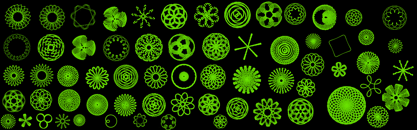
Experiments in creating organic shapes from particle motion and curves

  1. Particle set up for testing
SETUP_NPARTICAL_MOVE

2. Turn these particles into curves. There are two ways to do this.

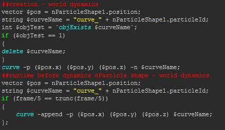
The first way involves expressions which allow the curves to be draw in real time. 3D Splanchnic has a tutorial showing what to put where. Watch it HERE.
code for expressions:
mel_Parts_to_curve
(update: if ( frame%10 == 0)  is simpler)
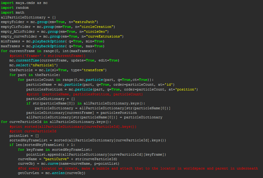
The second is a script. Bryan Woodward’s 'ParticletoTube' Script for Maya makes tubes out of particles by first creating curves. The first part of the script loops through the timeline frames for "theParticle" and then uses a nested loop to capture each "particlesPosition" and draws each curve form the "pointList". Read about the script HERE:.

Code:
partsToCurvesScript

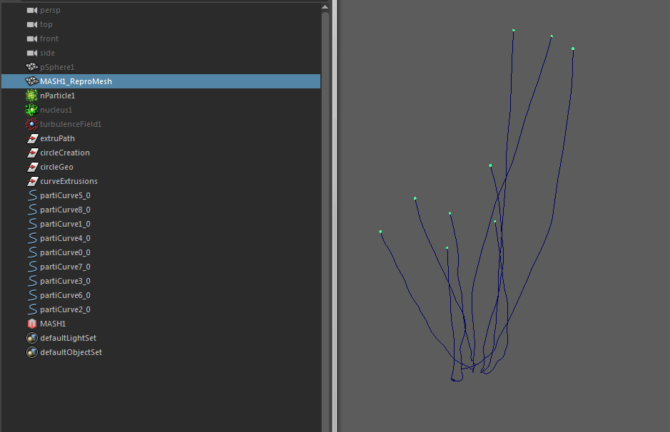
Now curves can be generated from the particle positions:
CurvesFromParticles02

nParticles_plus_mash.jpg

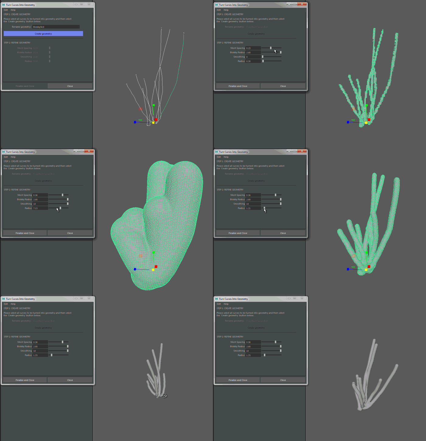
3. Finally a script is needed to turn these curves into organic looking geometry. Andrew Tubelli has a nice script for doing just that. Download it from his site HERE. The code simplifies what would be an annoying task by adding a UI with a few friendly sliders:
coral2

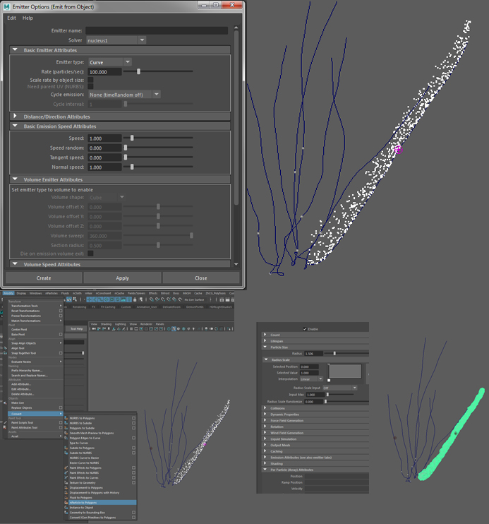
Completing the process via the Maya UI instead of the script:
nParticles_to_poly_old_way

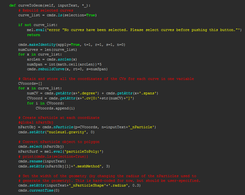
The code rebuilds the curves based on "arcLen", creates nParticles for the curves and evaluates a mel command to create polygons with the ability to set attributes Via a UI.


curveToGeoScript
Note: Some variable Changes are occasionally needed. For example the  curves generated by particles can be excessive - Try changing the (arcLen)*5 to say (arcLen)/5 or adding it into the UI.
I also needed to up the '.maxTriangleResolution' count.

Example:


4. A few shapes generated by moving a  passive collider around so as to alter the particle motion..
 
5. Now an experiment just from wires. I used a skull I previously modeled to draw curves on and then turned the curves into geometry.


Preiew render experiment
Some paint effect brushes added:
Sunday, 24 September 2017

Notes - Nodes & Mash – Maya

Here are some learning notes on creating a  plug-in for Maya, creating relationships with expressions and Maya's new python node. These are notes for me but perhaps others may stumble upon them and find them to be of interest. I'll probably change and grow this page as I learn a little more.
  1. Notes and links on how to create a Maya plug-in
Autodesk have an example Python Math Node. Here are my notes:
  • API module: import maya.openMaya
  • Proxy class access: import maya.openMayaMPx
  • Access to math module: import math
  • Variable for node name:  kPluginNodeTypeName = "nodeNameNode"
  • ID number for Node:        nodeNameNodeId = OpenMaya.MTypeId(0x00001)
  • Define subclass of existing class: class nodeName(OpenMayaMPx.MPxNode)
  • input = OpenMaya.MObject()
  • output = OpenMaya.MObject()
  • Override constructor using base: OpenMayaMPx.MPxNode.__init__(self)
  • plug = current input: def compute(self,plug,dataBlock):
  • Compute math example: result = math.sin( inputFloat )
  • Recompute plug and flag as clean: dataBlock.setClean( plug )
  • Maya pointer: return OpenMayaMPx.asMPxPtr( sineNode() )
  • Initialize method - input and output: nodeInitializer():
  • Add attribute here (ex- frequency or or amplitude): input = nAttr.create( "input", "in", ####)
  • Causes compute method to re-calculate - sets relationship: sineNode.attributeAffects( sineNode.input, sineNode.output )
  • Plug-in registration - Node Name/ID/Create Method/Initialize Method/Node Type: mplugin.registerNode( kPluginNodeTypeName, sineNodeId, nodeCreator, nodeInitializer )
  • De-register plug-in: mplugin.deregisterNode( sineNodeId)
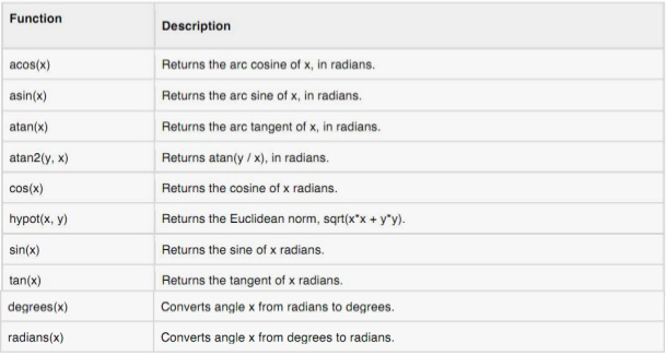
Understanding this we can now turn these python math functions into Maya nodes:
programming-with-python.jpg
2. Some links to various resources:
Classes:
  • Wrappers - math classes - m -(Quaternion, matrix, vector, points, vectors etc)
  • MObjects - data encapsulation (meshes, skin clustter nodes, curves  etc).
  • Functions Sets - mfn  - (access and manipulate data)
  • Proxy Class - mpx - - (abstractions - create new object types - inheritance)
For memory intensive process plug-ins need to be complied in c++. Here are some links:
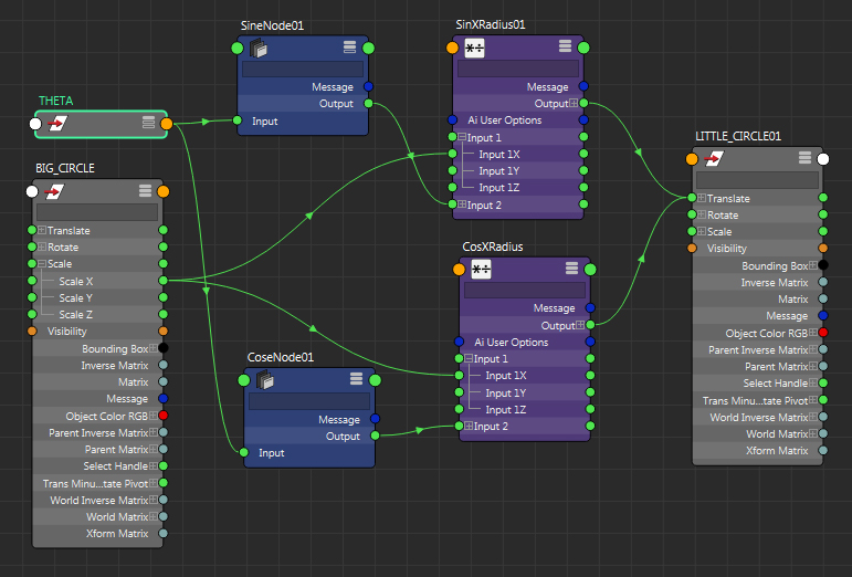
3. Example: Testing cosine node works.
radTimesSinCos01
radCosSonCirclesMayaNodes01
3. A Mel expression that does the exact same thing. A little bit less work :)
radTimesSinCos01_expression
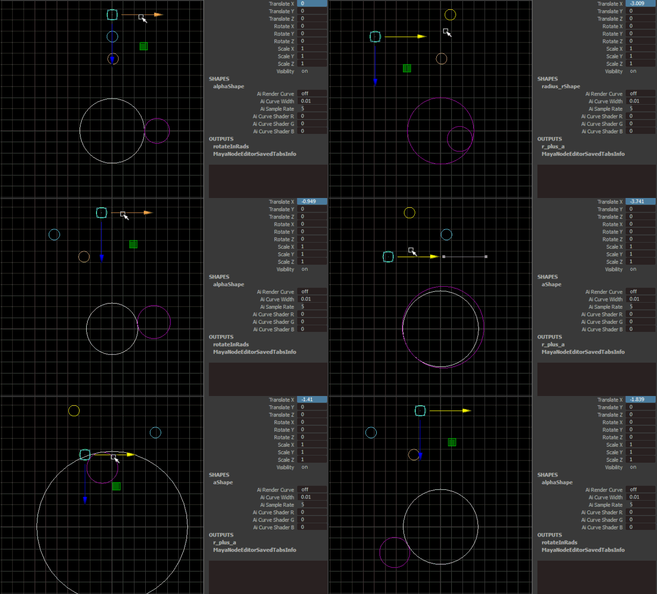
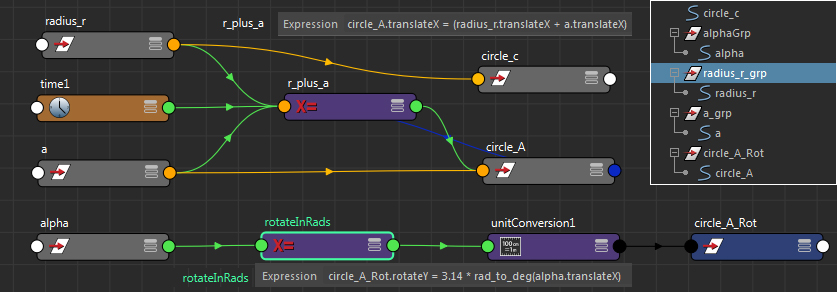
Two very simple expressions that create tangent circles (also known as kissing circles).
melExpression-KissingCirclesNWJ
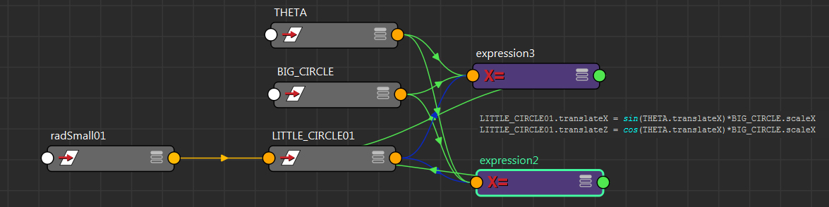
relationshipsWithExpressions
Nodes and expressions can build almost any kind of relationship we want.

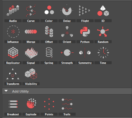
4. Mash Python node (Maya)
mashNodes01.jpg
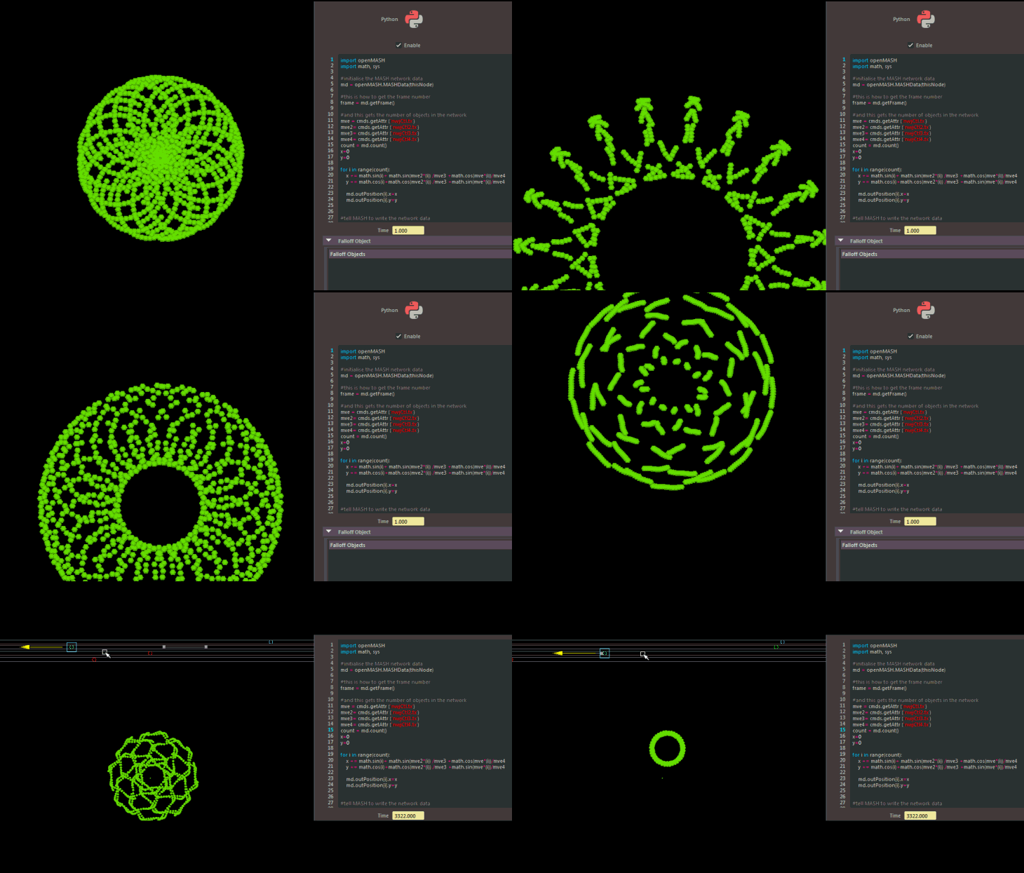
Python Node Test with controllers piped in as variables - Expression: (cos(t) + cos(6t)/2 + sin(14t)/3, sin(t) + sin(6t)/2 + cos(14t)/3) - (see article "Creating Art with Mathematics"). Perhaps usful patterns for stone placement or tiles of some sort.

paterns_maya_pythonNode_mash03


radCosSonCirclesMayaNodes04
paterns_maya_pythonNode_mash

Wednesday, 20 September 2017

Instancing test using Maya's Mash + Vray

This is a test for instancing grass with Mash in Maya. Very simple. Very quick. The settings are low and the render took next to no time. Perfect for previewing.


Oh how I am going to love using mash... and it has a python node!

I recently delved into writing some math nodes for Maya with python, (and compiling them in c++), with the idea of building something like what Rhino has with Grasshopper. It's turning into an excellent learning exercise. However, mash already has a lot of what I always wanted Maya to have. So... fun times ahead.

To test out some instancing using Maya's Mash:

1. Paint Effect for grass  - converted to polygon quads;
 
2. UV's organized 3X3. Vray 2 sided shader applied:
3. I thought I would throw in an old skull I poly modeled a long time ago. I decimated it in Zbrush, instead of using a displacement, and gave it a Vrays SSS shader. Here is a time-lapse of the Maya session:


4. In mash I instanced the grass over a plane and created a falloff object to mute the grass around the skull within a strength node. I also added a random node to the mix.

There is so much artistic control with this kind of procedural approach. Change, add, swap, blend, randomize, mute, duplicate etc.


Thursday, 10 August 2017

Thursday, 3 August 2017

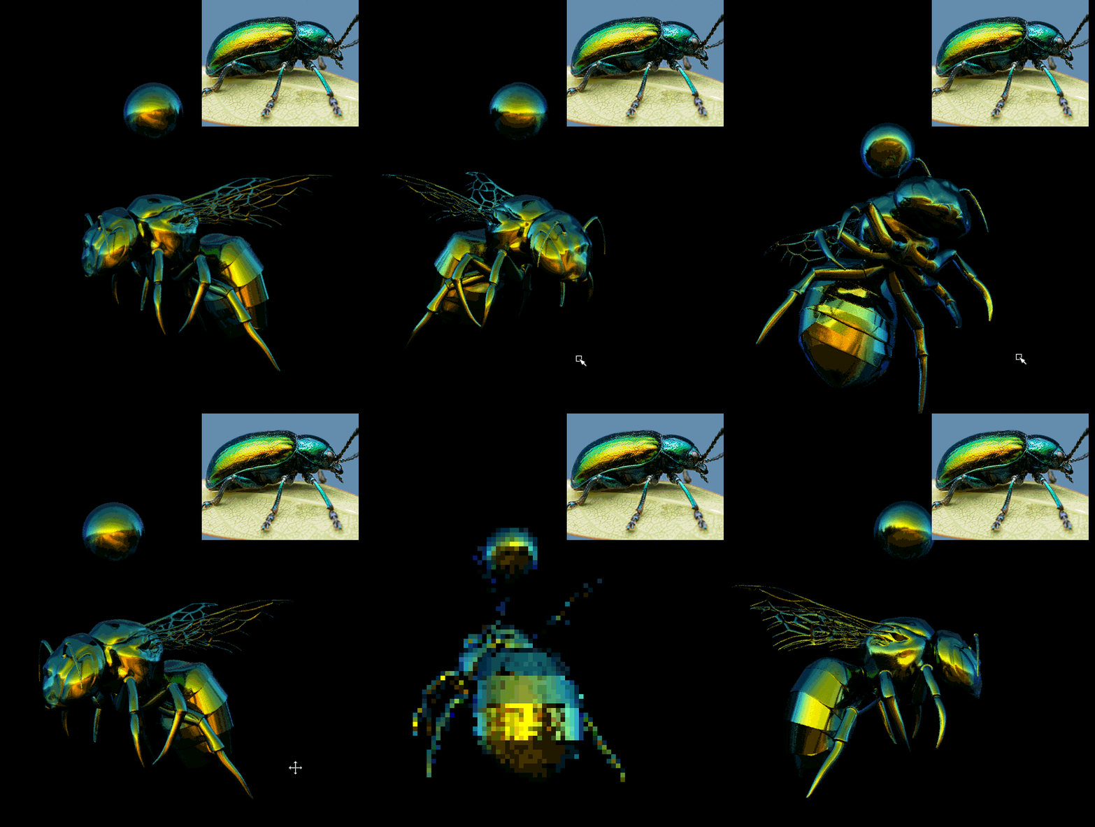
Metallic Carpenter Bee (Xylocopa (Lestis)) - Poly Modeling

A screen capture of my poly modeling session - the old fashioned way.

Initial tests for the Iridescent Bee Shader
First something super simple - Fall off curves for red green and blue. I was trying to match some photo reference of an iridescent beetle - reference image sourced from here - HERE

beeBeetleShd03 

Second - a test render using "Thin Film Interference". This is a work in progress but I like the general direction its going. More hair and some modeling tweeks are obviously needed. Photos of the actual bees can be found HERE. They're quite pretty. 


Shader test renders:

Wires:

 To be continued...

First Experiments using Grasshopper for Rhino

Grasshopper for Rhino – visual programming language/environment
 
pappusCh006
This is a blog post of notes made whilst using Grasshopper for the first time.
Circles and Triangles
Above: Solving for x²+y² = r² . Nodes used: I created two number sliders for variables - (Radius & Adjacent side), along with an expression evaluate node, square root node and vector node for XYZ.
Above: I created a Theta variable and plugged it into the Cosine(sideX) and Sine(sideY) functions, as degrees, and then into a Vector XYZ node. Math revision - SohCahToa
Above: Cos and Sin multiplied by radius.
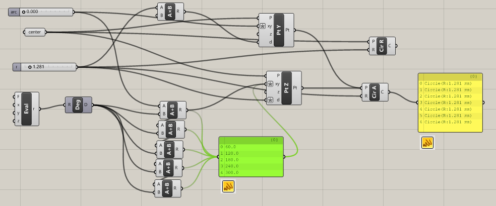
Above: I created a variable for the radius of pivot circle and multiplied it *2 to find the center point distance of the orbiting circle. I input the arc variable as radians - rad(x).  
Note: Input for expressions = x
Above: I added a 2nd circle with the expression Acos(1/2) and added the Arc variable to it. Note that the corresponding angle is 60° .

img_0577-11.png
Unit Circle reference image above from: Inverse Trigonometric/ArcCos.

I added more circles.
rotateArchCircles04b 
Above: By shift dragging connections we can connect multiple links and post-it note style lists help visualize inputs/outputs. We could also use the merge node.

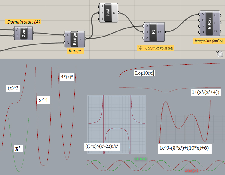
Function Curves 
Construct Domain node (DOM) - Start Value (-10) End Value (10) (= -10 to 10) 
Range Node - Give domain (-10 to 10) and steps (creates even spacing for steps within the domain - for example 10 will give a list of  steps each at 1/10th the domain).

graphsCreate2 
Interesting use of expressions for curves - see this article. I input a variety of variables, as number sliders, to create these pretty patterns.

interestingFunction02
Unit circle
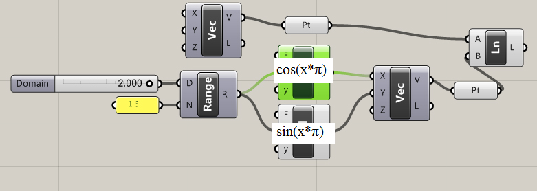
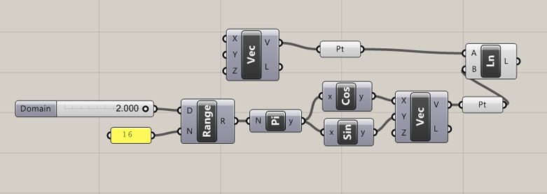
2 π = 360 degrees. 1 π = 180 degrees. I created two expressions, (cos(x* π) and sin(x* π), as vectors x and y to simulate the unit circle. The range node automatically generates a 10 number list within a domain (D). When we set the domain to 2 (2 π) we get a complete rotation of our unit circle. It works the same way with a node tree instead of an expression.
unitCircExpress 
unitCircle 
unitCircNodes

Pappus Chain 
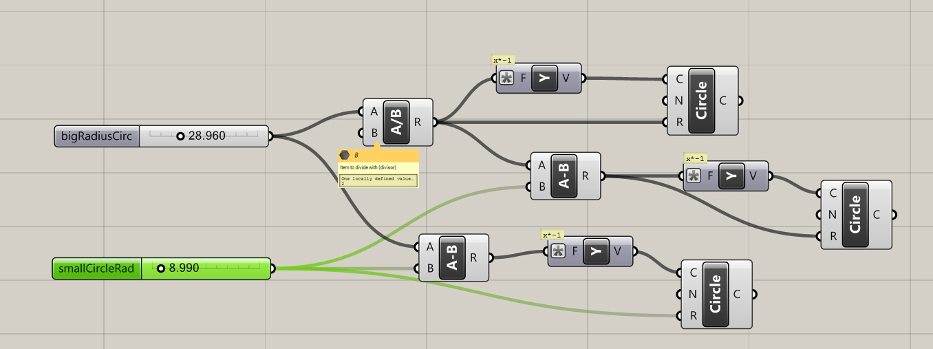
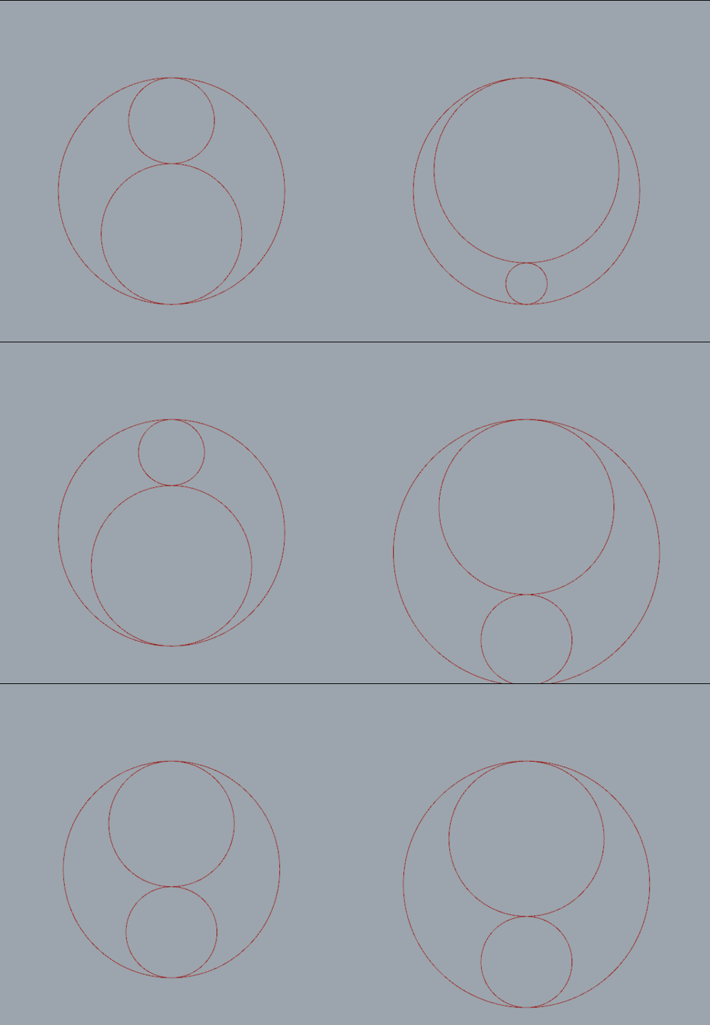
First I set up a simple relationship between three circles. As the radius of one circle increases the other decreases respectively. The magnitude of each  vector also increases or decreases to offset the change in radius . All three circles remain tangent.
papuisRing03c 
03_papuisRing03 
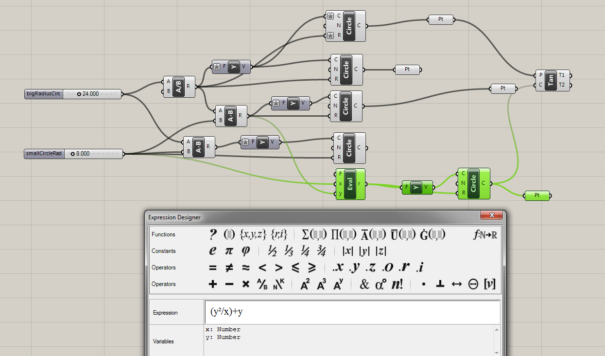
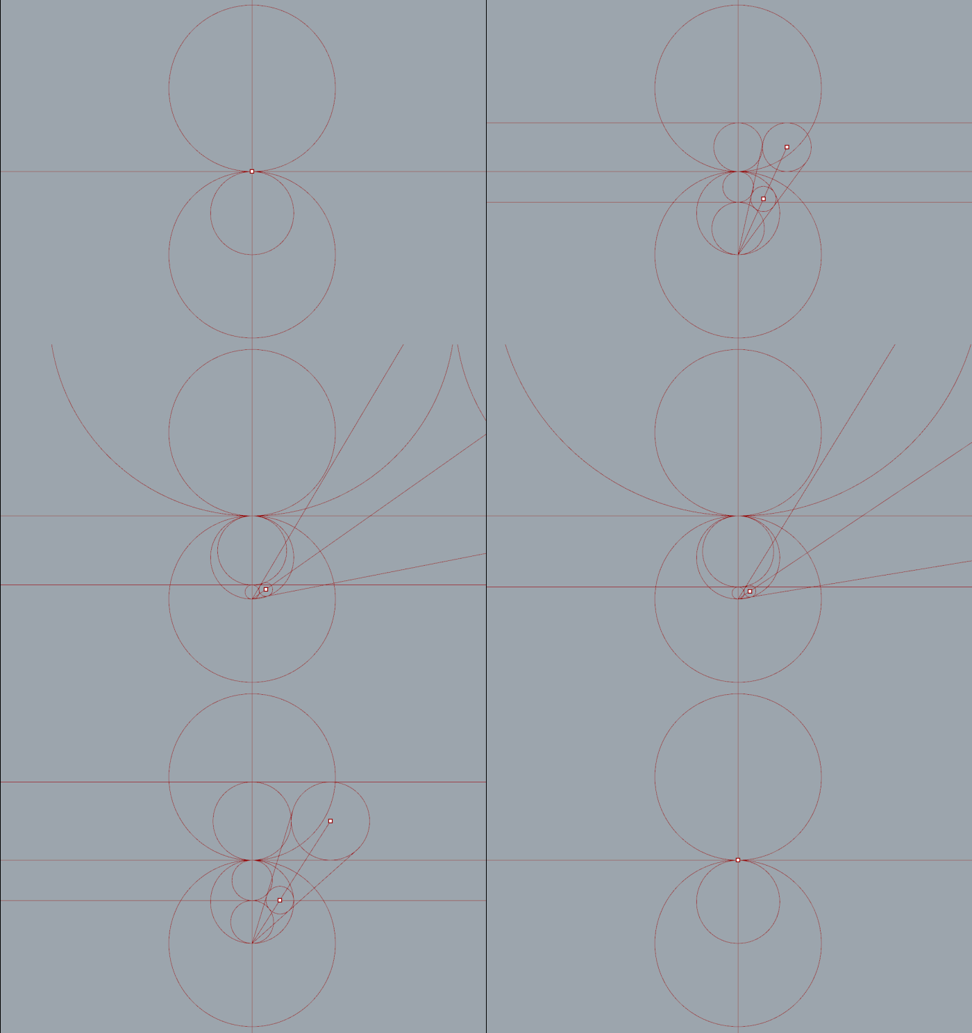
Next I wrote an expression to invert the top circle and tested it with some tangent lines.
papuisRing04 
03_papuisRing04
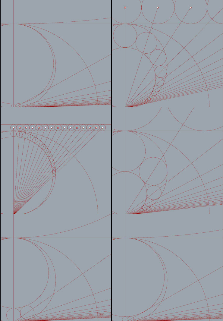
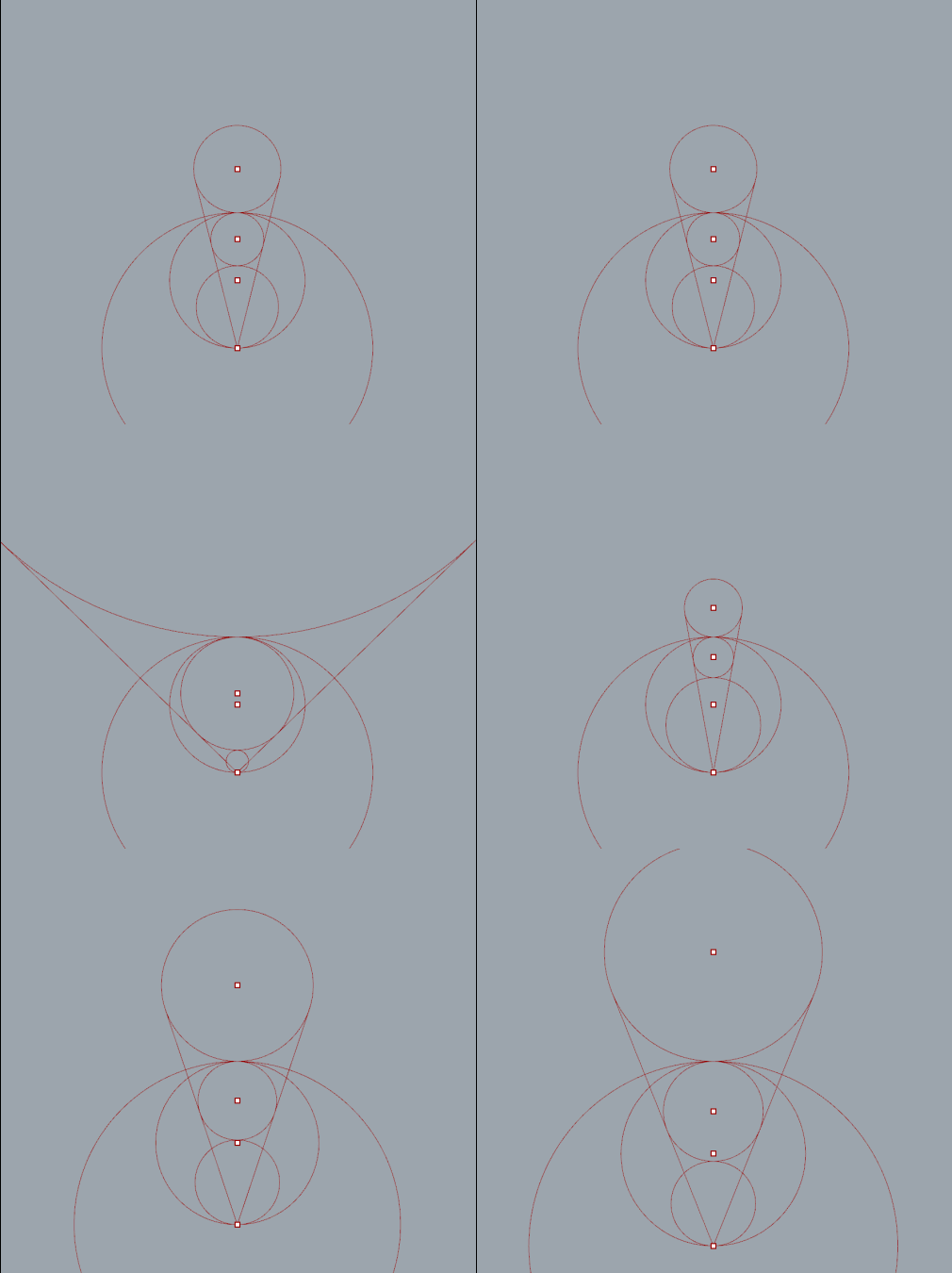
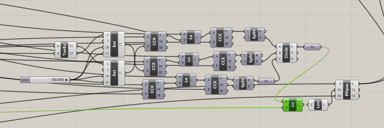
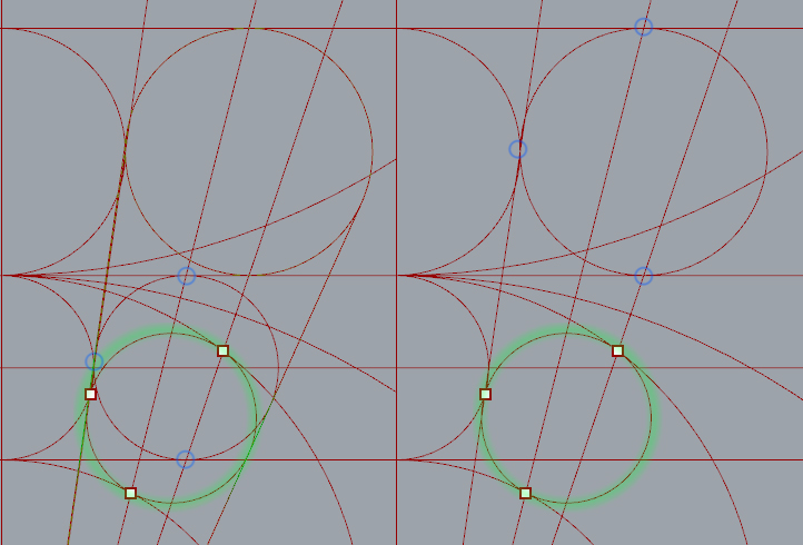
After a little bit of reading I found a number of ways to place the chain of circles. The most direct way is to calculate a three point circle from intersection points.

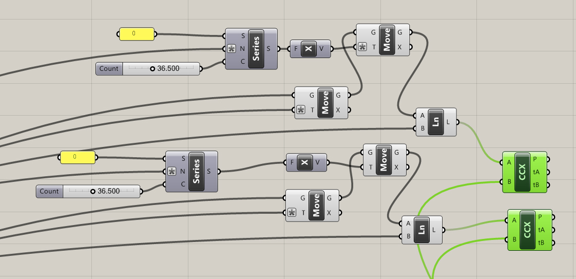
By extruding a number of tangent lines I was able to extract the necessary points using the curve|curve tool. Split nodes, set to integer 1, were needed to split the list generated when more then one intersection occurred.
papusCain02 
pappusChainIntersections 
03_papuisRing01 
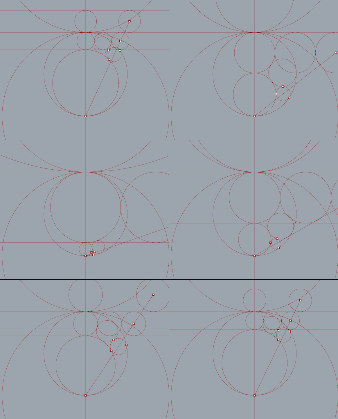
Circle number 2 added. Interesting but not very practical.
papChainN2
With one circle created there is enough information to generate an ellipse. Math Revision - x²/a² + y²/b² =1
papsCh008
More circles added.
pappusCh006

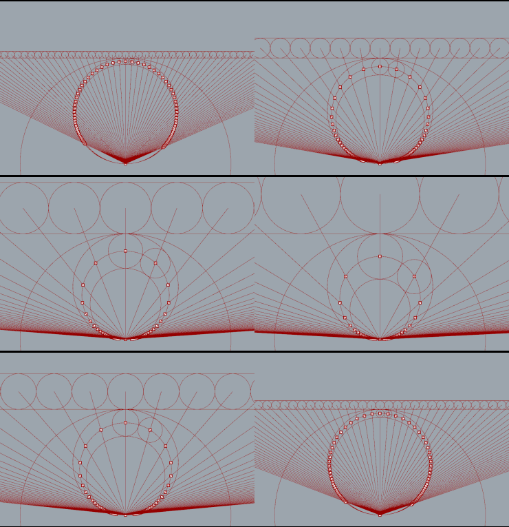
"Series" nodes iterate versions of the top circle with 2*radius for steps. Lines from each circles center point intersect with the ellipse.

papusCain03 
There are a bunch of interesting articles about the Pappus Chain. It would be a lot of fun to dive in more deeply and explore the mathematics properly. It's a very interesting subject. See links...
Reuleaux Skyscraper
It seems that everyone who uses Grasshopper for Rhino builds a skyscraper first. So why not. I'll try a simple mathematical shape - A Reuleaux Triangle. It's an interesting enough shape.

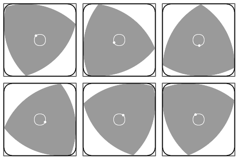
"Rotation of a Reuleaux triangle within a square, showing also the curve traced by the center of the triangle"
Rotation_of_Reuleaux_triangle
See Wikipedia entry
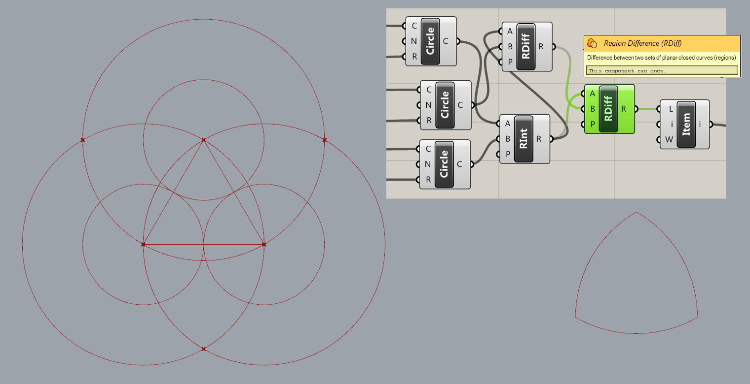
A Reuleaux Triangle is a shape formed from the intersection of three circular disks, each having its center on the boundary of the other two.reuleaux_circle01c
Above:  Before and after trim using region difference nodes to extract the reuleax triangle shape.

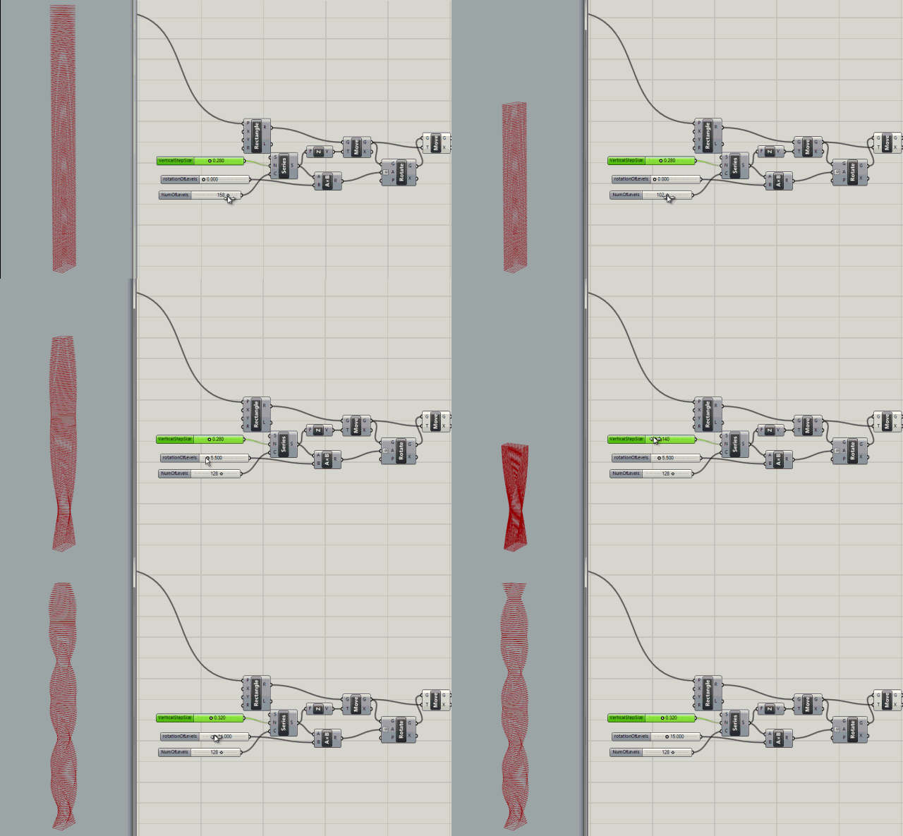
Twisting Node tree tests

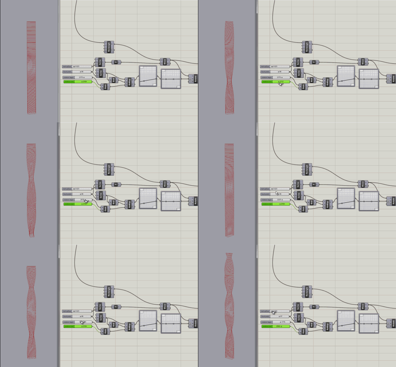
Series node with inputs to control the count (number of levels), the rotation of levels (in degrees), and the step size (size between levels)
.Untitled
More control added with rotation variables for rotating the the start and end of the building.
Untitled2
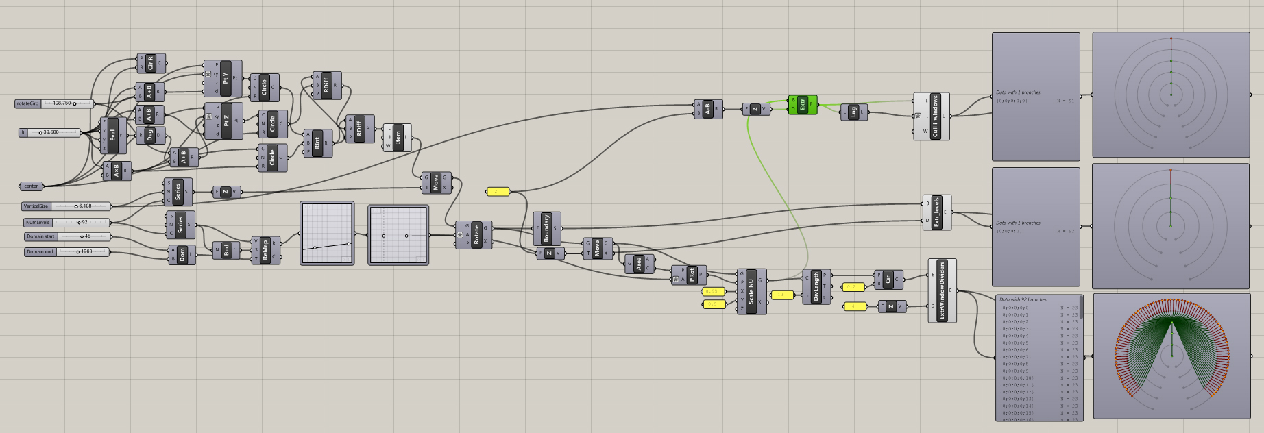
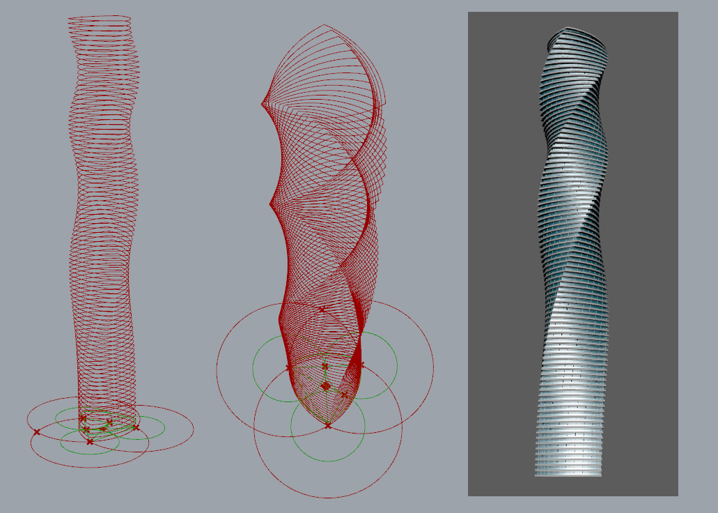
After a little more reading, and watching some youtube tutorials, I created my first grasshopper building. Not very interesting but it doesn't have to be. Its just for learning.
reuleaux_circle01D2
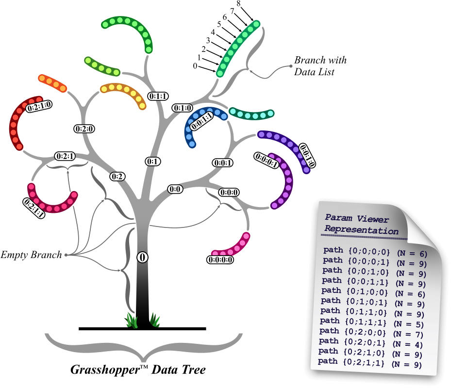
The node tree can be visualized with a param Viewer node which can display the tree visually - see node tree image.SkyScraperNodeTree
Grasshopper creator, David Rutton, has a video about data trees here.
datatree
Nodes of note for data manipulation/deconstruction:
 To be continued...